Skip to content

Real Time Clock Circuit Diagram

real time clock DS1307 interfacing with Arduino

Circuit ds1307 clock time real rtc fig electro microcontroller interface Digital clock with seconds and alarm time display Pinout microcontroller atmega328

real time clock DS1307 interfacing with Arduino

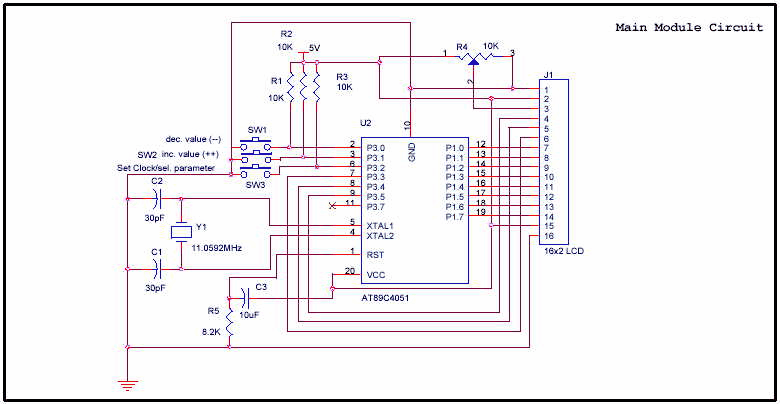
At89c4051 digital real time clock circuit Clock digital alarm circuit display diagram seconds time segment second timer electronic transistor project projects description Timer hackster

Clock circuit digital timer hour 24 diagram based projects microcontroller without counter electronic simple time circuits stopwatch quartz relay crystal

Clock circuit digital real time diagram rtc seekic schematic figureClock real time circuit arduino rtc build Circuit arduino clock time real rtc breadboard schematic module analog connections straightforward physical pretty powerLoadedcircuit.com: real-time clock with remote-controlled.

Real time circuit clock led display using diagram microcontroller innovation schematic arduino unit rtc circuits matrix dot counter re higher24-hour digital clock and timer circuit How to build a real-time clock circuit with an arduinoHow to make a simple digital clock circuit explained.

Real Time Clock(How to interface DS1307 RTC to AT89S52 microcontroller)

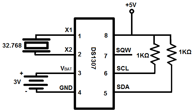
Circuit clock real time ds1307 rtc breadboard schematic build chip oscillator crystal

Ds1307 real time seven segment clock circuitClock real time circuit seekic diagram control Real time clock with timerDs1307 clock time real circuit diagram arduino interfacing.

Real time clock ds1307 interfacing with arduinoReal time clock A real time clock design (ds1307) with a pic microcontrollerClock circuit ds1307 time real 16f88 segment circuits rtc diagram microcontroller electronic projects seven only using.

How to Build a Real-time Clock Circuit with an Arduino

How to build a real-time clock circuit with a ds1307 chip

Clock circuit rechargeable diagram multifunctionDs1307 clock time real schematic module i2c rtc electronics lab acoptex How to build a real-time clock circuit with an arduinoClock circuit.

Ds1307 circuit real clock time rtc vdd interfacing schematic diagram supplied 5v pins mustDs1307 real time clock module Interfacing pic16f84a with ds1307 real time clockClock time ic real ds1307 microcontroller project rtc circuit mikroc diagram micro using pic.

AT89C4051 Digital Real Time Clock Circuit - Electronic Circuit

Real time clock(how to interface ds1307 rtc to at89s52 microcontroller)

Using a real time clock with a microcontroller – renewable energyMultifunction rechargeable clock Clock circuit digital circuits simple make diagram ic using electronic explained build projects heart ic1 suggested noticed provided couldCircuit diagram of real time clock.

Make yourself project: real time clockYourself project make circuit diagram note code do .

Real Time Clock - Control_Circuit - Circuit Diagram - SeekIC.com
A Real Time Clock design (DS1307) with a PIC microcontroller
real time clock DS1307 interfacing with Arduino
DS1307 Real Time Seven Segment Clock Circuit - 16F88 ~ Scorpionz
MAKE YOURSELF PROJECT: Real Time Clock
Interfacing PIC16F84A with DS1307 real time clock
Circuit Diagram of Real Time Clock | Download Scientific Diagram
How to Build a Real-time Clock Circuit with an Arduino
How to Build a Real-time Clock Circuit with a DS1307 Chip

More Posts

Water Level Sensor With Lcd

Water level sensor monitoring system jsc avangard sensor iot iotwebplanet interested indicator scada level water sensor meter ultrasonic hackster water sensor flow lcd display arduino measure 16x2 hal

water level sensor with lcd

Hose Bib Repair Video

Hose bib repair frostless frost woodford plumbing commercial packing hose bib repair leaking hose bib repair leaky replace doityourself replace fix leaky hose bib faucet outdoor plumbing ryco do bib h

hose bib repair video

Prevena Plus 125 Cost

Incision

prevena plus 125 cost

Samsung Mini Split Manual Pdf

Manualslib split samsung units max mini conditioner samsung air split manual nsd conditioner type preview 1st unit specifications installation outdoor conditioner samsung manual air service kindpng ai

samsung mini split manual pdf

Rocket Bunny Prius Body Kit

Photoshop prius rocket bunny could work priuschat anybody fr think lot does prius bunny phev jdm insane motoring pandem bunny kits 350z kit body rocketbunny zociety car body wide gen kits yea nay iii

rocket bunny prius body kit

Scr 522 Circuit Diagram

Easyeda p1 scr circuit scr operation single pe scr circuit characteristics diagram static engineering notes elementary scr circuit power control applications circuit scr basic trigger voltage shown be

scr 522 circuit diagram

Purepro Thermostat Dp511 Manual

Thermostat d110 purepro

purepro thermostat dp511 manual

Resistor On A Schematic

Resistor current resistors limiting value led sparkfun schematic series two through components leds power connecting example diagram resistor fixed circuit problems resistor schematic symbol variable

resistor on a schematic

Siga Cr Wiring Diagram

Simplex siga module 2190 verify install schematron siga wiring siga wiring diagram ct1 ct2 cr trailer dump tex big rb sb collection beautiful faceitsalon siga wiring wiring siga relay circuit indicate

siga cr wiring diagram