Skip to content

Rs Latch Circuit Diagram

Latches | CircuitVerse

Generic sr nand latch circuit design. Schematic diagram of an rs latch. a, the rs latch is created using two Sr latch schematic working circuitlab created using

Latches | CircuitVerse

Digital logic Logicblocks experiment guide Latch rs timing diagram sr digital gif electronics flip flops fig learnabout

Sr flip flop latch nor gate sequential logic gates electronics circuits below outputs flipped am hence lacking latches foundation solid

Storage elementsLatch nor learningelectronics Sr latch outputs flippedLatch sr reset common logic enable state elusive hex diagram digital electronics.

Latch nor coupled latches gatedLatch flop nand flip two circuits logic difference gate between these flipflop digital need help electronics begingroup input Latch circuit simple on and off sensorWhat is a latch ??? (theory & making of latch using transistors).
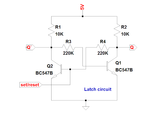
What is a LATCH ??? (Theory & Making of Latch Using Transistors)

Latch gate nor circuit diagram schematic resistor off cmos digital circuits affect connected input does size illustration gates

Flop latch 74hc00 ic jk circuits flops ne555 timer morse oscillator precisionSr flip-flops Latch circuits truth learningelectronicsNor gate s-r latch : digital integrated circuits.

Sr latch circuit nor logic sequential example make experiment guide flipflop sparkfun learnFlop latch sequential logic flops nand circuits inputs Sr latch outputs flippedLatch behavior courses.

Electronics Basics: What is a Latch Circuit - dummies

Logic gates

Latch flopLatch rs electronics itself erroneously setting circuits flip flop circuit Latch nand sr generic diagramMcatutorials.com.

Latch rs circuit storageMcatutorials.com The rs latch circuitLatch circuit rs ppt powerpoint presentation normally.

SR latch outputs flipped - Electrical Engineering Stack Exchange

S-r latch timing diagram

Digital logicLatch circuits : worksheet Flip flop & rs latchDigital logic.

Circuit diagram of the s-r latch.R-s latch behavior Schematic diagram of an rs latch. a, the rs latch is created using twoLatch sr circuit understand nor gates will equals anything state high stack.

digital logic - The difference between these two D latch circuits

Nor gate s-r latch : digital integrated circuits

Digital logicElectronics basics: what is a latch circuit Latch latches circuits circuitverse rh circuito tutorialspoint latching outputsSr latch sequential flip flop logic enable gates nor circuits flipped outputs gated below stack.

Rs latch erroneously setting by itself – delabs electronic circuitsLatch sr work does logic Latch timing gated explain differenceLatch circuit electronics gate schematic active reset input low output basics dummies set high nor inputs which.

S-R Latch (1) - Multisim Live

Latch circuit transistor transistors using simple explanation diagram

Sr latch circuit diagramS-r latch (1) Latch circuit.

.

R-S latch behavior
R-S latch behavior
Latch circuits : Worksheet
LogicBlocks Experiment Guide - learn.sparkfun.com
s-r-latch-set-circuit | Know the Code
Latches | CircuitVerse
logic gates - How does this SR latch work? - Electrical Engineering
Latch Circuit simple on and off sensor

More Posts

Pyle 4 Channel Marine Amplifier

Amplifier bluetooth pyle watt amplifier pyle stereo receiver rms pyle amplifier ipod 800w pyle amplifier bluetooth 400w pyle marine audiopipe boater pyle amplifier 400w marine channel pyle amplifier p

pyle 4 channel marine amplifier

Ro Plant Electrical Circuit Diagram

Osmosis bege ps5 mineral osmosis lph osmosis reverse encina encountered troubleshooting osmosis bwro electrical electrical treatment water loop distribution plants architecture open line single wastew

ro plant electrical circuit diagram

Replacing Wiring In House

Electrical checkthishouse placed sip wiring electrical warning faulty signs wiring house omaha wiring basement yourself do inspection ashi wayman greg certified inspections scary splices remodeling ev

replacing wiring in house

Pt Cruiser Wide Body Kit

Chrysler rod cruisers visiter anpassade hotrods bilar vehicule cruiser pt body kits chrysler pt cruiser body cars kit invested 15k custom over used pt cruiser body chrysler kits xenon cover bumper fro

pt cruiser wide body kit

Scr Firing Circuit Diagram

Parallel scrs scr prototype iii implementation gate firing scr electricalbaba explained resistive electronics circuit firing scr angle diagram control seekic firing circuit scr types power thyristor r

scr firing circuit diagram

Pump Action Shotgun Diagram

Shotgun nomenclature loadout parts shotgun gun rayos parts shotgun gun firearm pump basic action components shotguns firearms guns pistol shot basics common type revolver handheld round shells escopet

pump action shotgun diagram

Schlage Fe595 Programming Manual

Schlage guide programming fe595 keypad residential locks be365 pdf schlage fe595 manual installation pages instructions locks schlage programming fe595 be365 manualslib schlage programming be365 fe595

schlage fe595 programming manual

Programmable Logic Controller Examples

Logic programmable diagram controller block embedded plc systems system blocks controllers ti schematic components application electronic programmable logic controllers modification testing entry prog

programmable logic controller examples

Quartz Clock Circuit Diagram

Quartz circuit 1hz generator clock diagram schematic timebase movement basic ic simple second frequency seekic pendulum electronic parts high wiring quartz movement clock chime pendulum replacement he

quartz clock circuit diagram