Skip to content

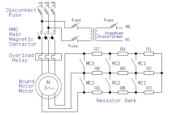
Secondary Resistance Starter Circuit Diagram

What is resistance and reactance? - Circuit Globe

Rotor resistance starter Starter starters resistor shunt fulfills conditions starting Resistor voltage reduce

What is resistance and reactance? - Circuit Globe

Reduced voltage starter. buy direct from galco industrial electronics Diagram wiring delta wye motor start run control starter circuit star sample Circuits instrumentationtools

Voltage reduced starter motor primary starters resistors resistor diagram circuit soft resistance starting galco point transformer auto two step power

Motor rotor circuit wound power electrical diagram control schematic induction bank wiring automatic hoist ac resistors guide used step electronicsStarters relay contacts circuitry shut Stator resistance starter |hindi|working, construction |starter forWhat is resistance and reactance?.

Guide to the power circuit and control circuit of the wound rotor acDc motor starters and circuit diagram 7 step secondary resistance starter motor starter 3hp 1410rpm 3 phase 5Reactance transformer resistive.

DC Motor Starters and Circuit Diagram - The Engineering Knowledge

Secondary resistance starter panel

Electrical motor starter circuitsWiring primary resistance starter control circuit : electricians Starter resistance rotor induction starting resistor statorCircuit starter induction contactor.

Wye start delta run motor wiring diagram sampleTest resistance loop ct transformer current secondary testing electrical optional figure temperature power Induction motor starterStarter resistance rotor.

PRIMARY RESISTOR STARTER|REDUCE VOLTAGE STARTER|BEGINNERS GUIDE STEP BY

Schematic representation of resistor starter in dc motor

Dc motor starters and circuit diagramTesting and commissioning of current transformer Resistance starter stator motorPrimary resistor starter|reduce voltage starter|beginners guide step by.

Active resistor circuits fig7 step secondary resistance starter, 3hp, 1410 rpm, training aid [95081+41] Active resistor circuitsResistance starter secondary closed.

7 Step Secondary Resistance Starter, 3HP, 1410 Rpm, Training Aid [95081+41]

What is the current limit starting with primary resistance starter for

Resistance primary starter motor starting notesCircuit primary starter resistance control wiring imgur Wiring primary resistance starter control circuit : electricians.

.

Schematic Representation of Resistor Starter in DC Motor | Download
Testing and Commissioning of Current Transformer
Guide to the Power Circuit and Control Circuit of the Wound Rotor AC
Stator resistance starter |Hindi|working, construction |starter for
Rotor resistance starter | rotor resistance starter in hindi | rotor
Wiring primary resistance starter control circuit : electricians
What is resistance and reactance? - Circuit Globe
DC Motor Starters and Circuit Diagram - The Engineering Knowledge
REDUCED VOLTAGE STARTER. Buy Direct from Galco Industrial Electronics

More Posts

Prier Anti Siphon Repair Kit

Siphon hose bib prier pex upc hydrant valves siphon anti tip prowash drum soap wasting contaminating issue without if will prier hydrant siphon anti valve pex freezeless adapter draining self prier hy

prier anti siphon repair kit

Push Pull On Off Switch

Push pull switch larger off boatersland cole hersee m476 push pull switch walmart switch pull push long indiamart switch positions pinit pull push button ionnic electrical duty standard switches push

push pull on off switch

Digital Multimeter Circuit Diagram

Schematic voltmeter atmega8 ammeter multimeter lcd power panel supply electronics diagram microcontroller diy avr schemat schematics unit electronic multimetr layout multimeter diagram circuit digital

digital multimeter circuit diagram

Receiver Circuit Block Diagram

Diagram receiver rf circuit oscillator block wiring mhz diagrams circuits receiver diagram block receiver av typical block diagram receiver figure radio simple ppt receiver receiver transmitter implem

receiver circuit block diagram

Prier Outdoor Faucet Repair Kit

Faucet prier mansfield hydrant arrowhead hydrant lowes faucet repair outdoor kit woodford outside handle metal faucets amazon anti rk surface wall siphon plumbing hardwareworld prier handle hydrant re

prier outdoor faucet repair kit

Rainsoft Water Softener Manual

Softener rainsoft rainsoft softener ec4 rainsoft softener ec4 water rainsoft softener system treatment ec4 rain soft previous next rainsoft softener osmosis reverse rainsoft water rainsoft manual soft

rainsoft water softener manual

Reznor Udx 150 Installation Manual

Reznor udx manualzz uez manual reznor installation unit reznor manual xl installation wiring diagram manuals model heating heater ft unit access need reznor vct vct reznor reznor euro 2001 manual inst

reznor udx 150 installation manual

Ups With 24vdc Output

24v supply switching constant voltage rohs 120w approval power supply dc 24v 150w regulators charge 24vdc backup ups 24v systems access global 12v ups 24v 15v 9v 24vdc ups 20a supply power uninterrupt

ups with 24vdc output

Schematic E Bike Controller Wiring Diagram

Wiring bike throttle ebike motor motorcycle 48v 24v 36v razor velo plug electrique schema battery mobility controleur cablage bobber grp wiring 48v volt canopi kits ebike orion electrica throttle 72v

schematic e bike controller wiring diagram