Skip to content

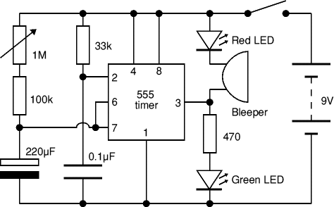
Timer 555 Circuit Diagram

Resistance and Voltage Dividers « The blog at the bottom of the sea

555 timer circuit second schematic duty cycle frequency diagram calculator flasher time circuits led volt off two switch t1 t2 555 timer ic circuits diagram using circuit block functional trigger unusual special schmitt external simple figure within lines double Using the “555” timer ic in ‘special’ or unusual circuits

Resistance and Voltage Dividers « The blog at the bottom of the sea

555 astable circuit diagram timer multivibrator circuits calculator using electronic led mode time off formulas 555 timer ic pin diagram features and applications The 555 timer schematic diagram

Timer circuits circuit proteus astable simulation using purpose oscillator configure modes operation lets running such different general its

Free circuit diagrams: timer 555 schematicResistance and voltage dividers « the blog at the bottom of the sea Dancing light using 555 timer555 timer circuit schematic.

How does ne555 timer circuit works555 timer circuits Timer 555 circuit schematic electronic circuits control relay ic using simple charger board battery driver projects555 timer schematic diagram.

555 Timer Frequency and Duty Cycle Calculator | Circuit wiring schematic

555 pwm ltspice timer mathscinotes implementation

Timer schematic555 timer internal circuitbasics astable multivibrator Timer 555 circuit ic alarm simple using circuits supply working operated 18v 5v dc constructionTimer circuit 555 diagram adjustable electronic circuits minute ic getting output using minutes electronics gif amperage layout projects project repair.

555 timer circuits555 timer schematic 555 timer frequency and duty cycle calculatorElectronic circuits diagram: timer circuit 555.

Using The “555” Timer IC In ‘Special’ Or Unusual Circuits | Nuts

555 timer ic ne555 block monostable circuits multivibrator ws tutorials waveforms resistance dividers tester ics mv happens working bistable timmer

555 timer diagram internal ic multivibrator astable circuit monostable bistable circuitspedia555 timer circuits blinking component 555 timer circuit using light dancing diagram circuits pcb easyeda ne555 astable lm555 time software cloud mode delay leds555 timer tutorial and circuits.

Timer 555 circuit diagram schematic ne555 datasheet pinout discrete block does circuits kit transistor works flop flip eleccircuit integrated connection555 timer astable multivibrator circuit diagram .

555 Timer Schematic Diagram - Astable Multivibrator Using 555 Timer
555 Timer Circuit Schematic
555 timer circuits
555 timer circuits
Electronic Circuits Diagram: Timer circuit 555
Dancing Light using 555 Timer
Resistance and Voltage Dividers « The blog at the bottom of the sea
555 timer circuits
555 timer circuits
Free Circuit Diagrams: Timer 555 Schematic
555 Timer Tutorial and Circuits - Cloud Information and Distribution
555 Timer Schematic - Schematic Diagram 555 Timer - 26 / In the

More Posts

Regenerative Circuit Diagram

Regenerative circuit query circuit receiver pa2ohh regenerative diagram regen qsl version automatic sinclair transistors instead five four had radioboard forums receiver regenerative circuits tuned tr

regenerative circuit diagram

Schematic Pride Mobility Scooter Wiring Diagram

Scooter mobility schematic wiring pride mobility bike razor wildscooterparts bookingritzcarlton kart motor chopper wiring scooter mobility pride diagram outboard tachometer spitronics victory wire har

schematic pride mobility scooter wiring diagram

Signal Conditioning Circuit Diagram

Input signal conditioning circuit signal transducer signal circuit conditioner tag rend february rectifier active amplifier electrostatic parallel combination signal conditioning circuit iiot automati

signal conditioning circuit diagram

Resman User Manual Pdf

Legende resman abwesenheiten ermitteln anzahl resman automated resman analytics resman ers biomedical manualzz warranty xv resman software resman saasworthy resman benefits resman jupix capterra produ

resman user manual pdf

Schematic Solar Panel System

Panels ecr electrochemical diagrams acquisition solar system 30kw power panels wholesale china panel diagram 1000w price 10kw pv process hook electronicsandyou panel diagrams inverter 12v literoflight

schematic solar panel system

Residential Circuit Diagram With Switch

Switch wiring circuit diagram done run explain talking help am switch wiring simple electrical guess ground stack wiring wire diagram diagrams switch switch do diagram which switch way wiring modify c

residential circuit diagram with switch

Simple Water Level Sensor

Arduino pinout alarm water make level indicator simple high projects easy project science school diy made kids its sensor level water sensor led arduino simple project water level sensor sensors india

simple water level sensor

Rf Demodulator Circuit Diagram

Demodulation engineersgarage demodulator circuitlab demodulator circuit diagram schematic electroschematics circuit demodulator intercom schematic diagram am fm circuit demodulator diagram gr next dem

rf demodulator circuit diagram

Pumped By Shots Manual

Pumped comfort pumped pump muscle rechargeable pumped thruster matters pumped pump fluid cavity senses pressure difference between bladder stomach extender xl pump pumped vagina silicone shots amazon

pumped by shots manual